User documentation
This section describes how to use the FXU to efficiently develop applications according to MDE methodology. The whole process can be described in few steps:
User Guide for the FXU 2.0
1. Creating UML model
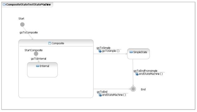
Preferred tool to create UML model is Rational Software Architect 7.5, but it can be any other tool which is able to export model into UML2.1 format (.uml extension). In this section it will be described process of creating UML model using Rational Software Architect 7.5. Firstly, create UML model containing class diagram
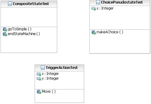
and state machine diagrams.
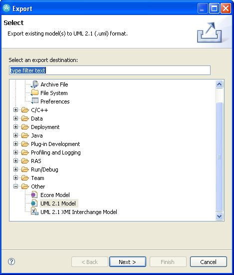
Next export model to UML2.1 format.
File->Export opens Export Window. Choose Other->UML 2.1 Model and click "next" button.
Specify UML model to export and destination path:
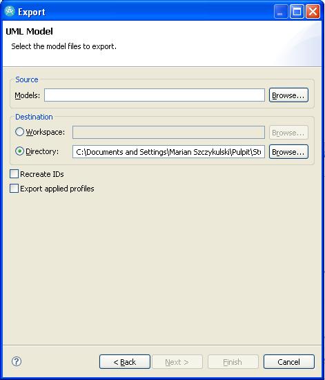
Now the UML2.1 model file is created in specified path. It will be used in next steps to generate C# code.
2. Loading UML model to FXU
Firstly, start FXU by double-clicking Fxu.jar file.
Next click File->Open and select UML2.1 model file. It may take few seconds to load UML model. Model is displayed as tree containing all nodes specified in uml2.1 model file.
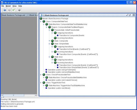
Now, the model has been read and is ready for validation and code generation.
3. Validating UML Model
This is an optional step, because model is being validated always before code generation. To validate click Model->Validate Model. FXU will display appropriate information about validation result.
4. Generating C# Code
To generate code click Model->Generate C# Code. Generation window will be displayed.
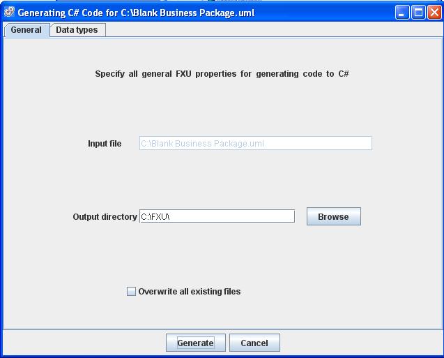
It has two tabs. First contains general information:
- Input file - it cannot be changed.
- Output directory - directory where generated code will be placed
- Overwrite all existing files - select to overwrite existing files in output directory.
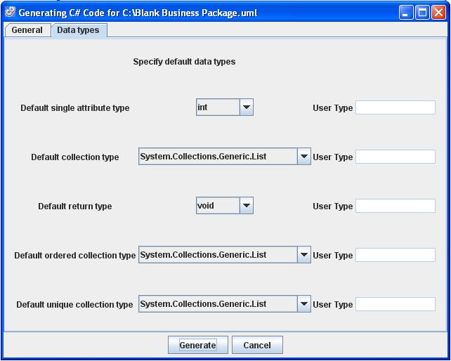
Second tab contains information about default data types used in generated code:
- Default single attribute type
- Default collection type
- Default return type
- Default ordered collection type
- Default unique collection type
Note, that this data types are used only if they are not specified in UML model created at first step.
There will be created two subdirectories in output directory:
- lib
- it contains:
- FXU.dll
- FXU.dll.manifest
- log4net.dll
- log4net.dll.xml
- src - it contains namespace directories, where C# files are located. For example:
- Blank_Business_Package
- ChoicePseudostateTest.cs
- CompositeStateTest.cs
- TriggerActionTest.cs
- Blank_Business_Package
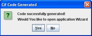
Click Generate to start process of code generation. After it is done question about starting application wizard will be displayed.
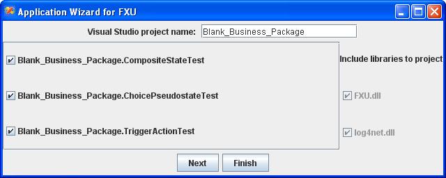
5. Creating Visual Studio 2008 Project
- Specify project name
- Select classes that project will contain
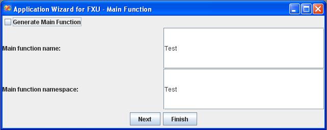
At second step select if Main function is to be generated. If so:
- Specify name of class containing Main function - class will be created by wizard.
- Specify name space of class containing Main function
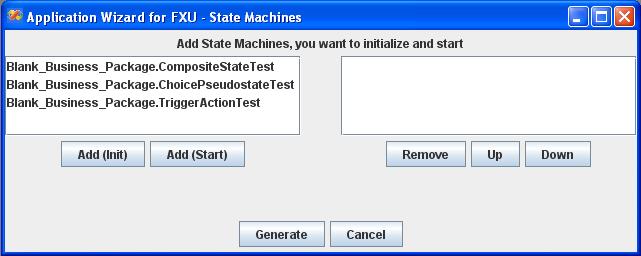
In third step:
- Specify state machines which will be initialized (by selecting appropriate class containing state machine and clicking Add(Init) button) and started (by selecting appropriate class containing state machine and clicking Add(Start) button).
It is possible to specify order of initialization and starting state machines.
Note, that starting state machine must be placed after initialization this state machine.
Click Generate. Now project is created and ready to open and run in Microsoft Visual Studio 2008.
Application Wizard will create:
- Microsoft Visual Studio files
- Blank_Business_Package.csproj - project file
- Blank_Business_Package.sln - solution file
- Optionally, C# files with main function and namespace directories
User Guide for the FXU 3.0 - 5.0
1. Creating UML model with stereotypes
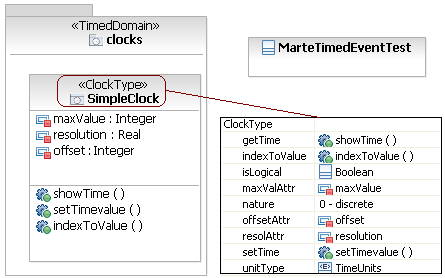
In the first step, an UML model has to be created. In the example IBM Rational Software Architect 9.0.5 has been used, but it is possible to use any CASE tool which supports exporting the UML model into the UML format of Eclipse (uml 2.2 format). At the beginning, a class diagram has to be created (Figure 1). In the example there are two classes: MarteTimedEventTest, which has neither operations nor attributes, and SimpleClock class in a package clocks. The second class has a ClockType stereotype from the MARTE::Time profile, which tag values are shown in the frame in the picture below. Moreover the package clocks has a TimedDomain stereotype.
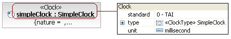
The SimpleClock class defines a new type of clock. The stereotype ClockType and its tag values specify properties of this kind of clock. But in order to use this type of clock it is necessary to create an instance of the class. Therefore, in the next step, an object diagram for the clocks package is created (Figure 2). Only one object is created and it will be used by the exemplary state machine.
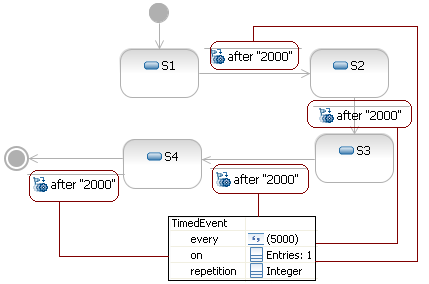
The third part of the UML model is a state machine diagram for the MarteTimedEventTest class (Figure 3). It consists of four simple states. The transition between those states are triggered by a time event which has a TimedEvent stereotype from the MARTE::Time profile. The first event is generated after 2000 units of time on a clock specified by ōonö tag value of the stereotype TimedEvent. Next events will be generated after every 5000 units of time, as it is specified by ōeveryö tag value.
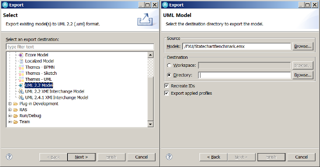
The created model has to be exported to the UML format of Eclipse. It can be done by clicking ōFile-Exportö, selecting ōUML 2.2 Modelö on the ōOtherö section and following wizardÆs steps. It is important to select an ōExport applied profilesö option in the second frame. Thanks to this, the FXU Generator will be able to read all applied profiles in the model and generate appropriate C# code.
2. Loading UML model to FXU Generator
The generator can be launched by double clicking the ōFXUGenerator5.0.jarö file. Before launching the generator, ensure yourself that the MARTE::Time plug-in is provided by checking the ōFXUGenerator3.0_libö folder. It should contain the ōMarteTime.jarö file.
In order to load the model click ōFile-Openö and select a file with the exported model in your file system.
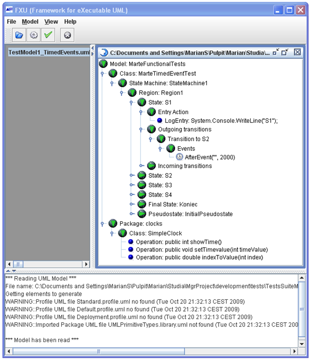
Now, the model is loaded and visualized in a tree-like form which represents the real hierarchy in the original UML model (Figure 5). It is important to check logs in the result frame at the bottom of the main window. There are a few warnings. They indicate that the FXU loader has not been able to find files with UML profiles (Standard.profile.uml, Default.profile.uml, Deployment.profile.uml), which are applied in the model. In this case, stereotypes from these profiles were not used, so warnings can be ignored.
3. Validating UML Model
In order to perform model validation click ōModel-Validate Modelö. The dialog window with a message ōModel is validö should appear. In the result frame, at the bottom of the main window, additional messages should appear. Apart from messages from the FXU model loader, described earlier, there is one warning:
WARNING::Parameter MarteFunctionalTests::clocks::SimpleClock::indexToValue::value - Name of the element is a C# contextual keyword.
It indicates that there is a parameter named ōvalueö, which is a C# keyword. But in this case, this parameter is a return parameter of an operation SimpleClock::indexToValue and it will not appear in the generated code. Therefore these warnings can be ignored.
4. C# code generation
In order to generate C# code from the loaded model click ōModel-Generate C# Codeö. In the generation window there is a possibility to configure some features of the generated code such as algorithms for the FXU Runtime Environment, a destination path, default data types or an application logger configuration. Next four pictures show every tab in the generation window.
Default values can be used and by clicking the ōGenerateö button C# code can be generated. However, sometimes it would be helpful to choose other possibilities. They are listed and described shortly below.
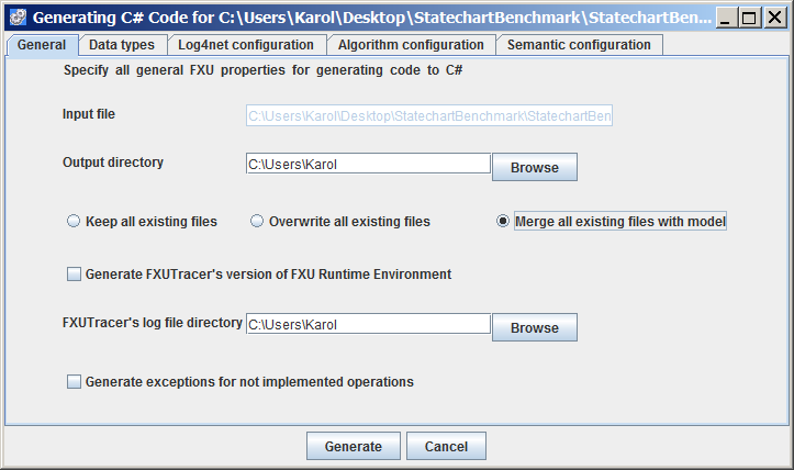
First Tab (General - extended in the FXU 5.0)
- Output directory ¢ indicates place in the file system where generated C# code will be stored.
- Keep all existing files ¢ if selected, all existing files of the same name in the output directory will be kept.
- Overwrite all existing files ¢ if selected, all existing files of the same name in the output directory will be replaced by new ones,
- Merge all existing files with model ¢ if selected, all existing files in the output directory will be merged with associated classes of the model (new option in the FXU 5.0).
- Generate FXU TracerÆs version of FXU Runtime Environment ¢ it allows to use the FXU Tracer in order to follow the execution of state machines in the generated application.
- Generate exception for not implemented operation ¢ if selected, there will be exceptions generated for unimplemented methodsIf not selected, dummy return values for unimplemented methods will be generated.
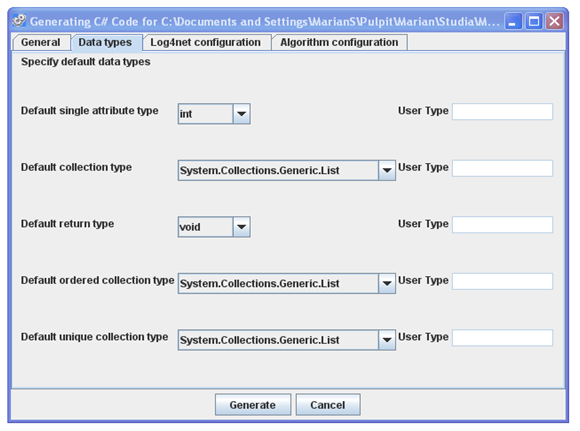
Second Tab (Data Types)
- Default single attribute type
- Default collection type
- Default return type
- Default ordered collection type
- Default unique collection type
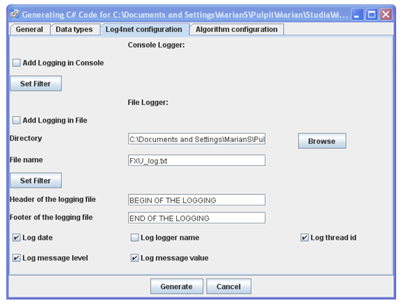
Third Tab (Log4net configuration)
- Add Logging in Console
- Add Logging in file
- Header of the logging file
- Footer of the logging file
- Logging information
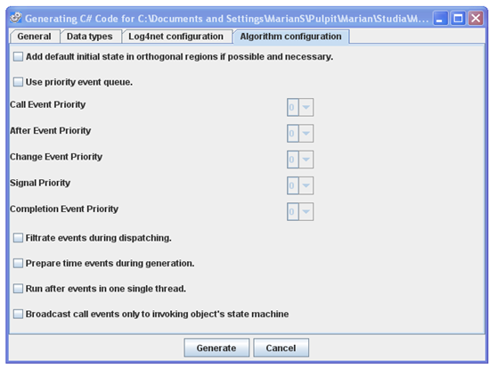
Fourth Tab (FXU 3.0 Algorithm configuration)
- Add default initial state in orthogonal regions if possible and necessary ¢ if selected, the generator will fix the error situation when orthogonal region has no initial state.
- Use priority event queue ¢ if selected, a priority event queue will be used instead of a FIFO queue in the FXU Runtime Environment. There is also a possibility to configure priorities for different event types (0 is the highest) (new option).
- Filtrate events during dispatching ¢ if selected, events will be dispatched only to those state machines in which they are really used (new option).
- Prepare time events during generation ¢ if selected, time events for a state will be calculated during the code generation phase, but not during an application execution (new option).
- Run after event in one single thread ¢ if selected, there will be one single thread for all after events that might occur in a state instead of separate thread for every after event (new option).
- Broadcast call events only to invoking objectÆs state machine ¢ if selected, call events for non-static operation in a class will be dispatched only to state machine of an object that has invoked the operation (new option).
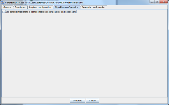
Fourth Tab (FXU 4.0 Algorithm configuration)
- Add default initial state in orthogonal regions if possible and necessary ¢ if selected, the generator will fix the error situation when orthogonal region has no initial state.
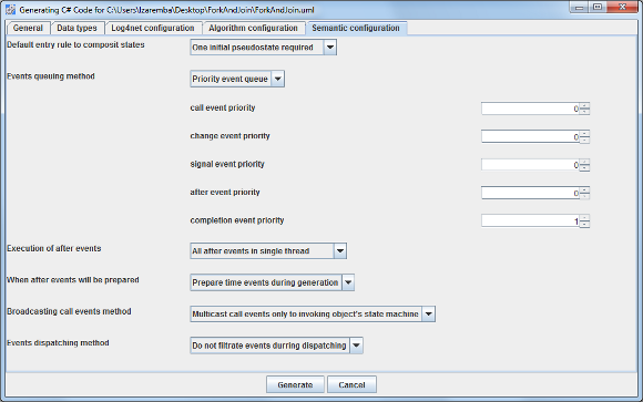
Fifth Tab (FXU 4.0 UML sematic configuration)
-
Default entry rule to composit states:
- the "One initialpseudostate required" item selected - a state machine performs a default entry to the initial pseudostate in a region, if only one initial preudostate exists in the region. Otherwise, the region is considered as completed already after entry.
- the "Exit if no initial pseudostate" item selected - a state machine performs a default entry to the initial pseudostate in a region, if only one initial preudostate exists in the region. Otherwise, the state machine is considered ill-formed and the execution is stopped.
- the "Start from most appropriate state" item selected - a state machine performs a default entry to the initial pseudostate in a region, if only one initial preudostate exists in the region. Otherwise, it performs an entry to the state in the region such that it is not a target of any transition. If such state doesnÆt exist, the region is considered as completed already after entry.
- Events queuing method:
- the "Priority event queue" item selected - a priority event queue will be used in the FXU Runtime Environment. There is also a possibility to configure priorities for different event types.
- the "Plain event queue" item selected - a FIFO queue will be used in the FXU Runtime Environment.
- Execution of after events:
- the "All time after in single thread" item selected - there will be one single thread for all after events that might occur in a state.
- the "Each after event in separated thread" item selected - there will be a separate thread for every after event that might occur in a state.
- When after events will be prepared:
- the "Prepare tiem events during generation" item selected ¢ time events for a state will be calculated during the code generation phase.
- the "Prepare tiem events during execution" item selected ¢ time events for a state will be calculated during an application execution.
- Broadcatsing of call events method:
- the "Multicast call events to invoking object's state machine" item selected - call events for non-static operation in a class will be dispatched only to state machine of an object that has invoked the operation.
- The "Broadcast call events to all state machine" item selected - call events wil be dispatched to all state machines.
- Events dispatching method:
- the "Do not filtrate events during dispatching" item selected - events will be dispatched to all state machines.
- the "Filtrate events during dispatching" item selected - events will be dispatched only to those state machines in which they are really used.
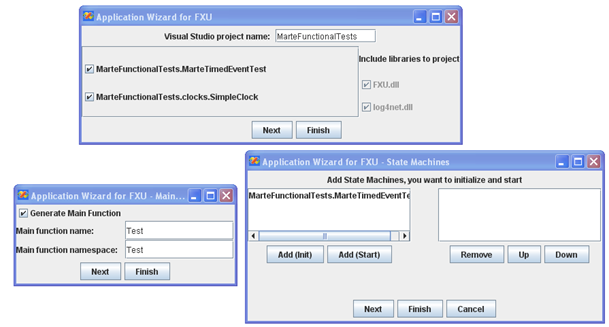
5. Creating a Visual Studio 2008 project (also VS 2010 in 4.0 version of FXU)
The last step is a Microsoft Visual Studio 2008/2010 project generation. It is an optional step and can be omitted. Figure 10 shows first three windows of the FXU Application Wizard. There is a possibility to specify a project name, to generate the Main function and specify its containing class namespace and name. In the third window of the wizard, selected state machines can be initialized and started.
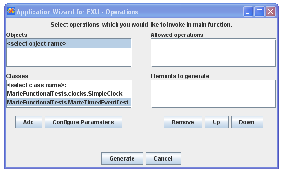
In the last window of the wizard there is a possibility to specify which operations have to be invoked in the Main function. There is also a possibility to configure attributes for invoked operations. The window is shown in the figure 11.
The whole project is developed under the supervision of Anna Derezińska (2006-2018)
Institute of Computer Science, Warsaw University of Technology